


Click on a photograph to enlarge an image.
Click on the hyperlink to see other Notable Orders from the 1950s.
If you remember designing, machining, fitting, installing, maintaining, or working with this machine please share your memories at the bottom of the page by clicking on the words Add a comment about this page.


Comments about this page
Chippy, the common denominator is that they were both fine engineers in their own right. John B
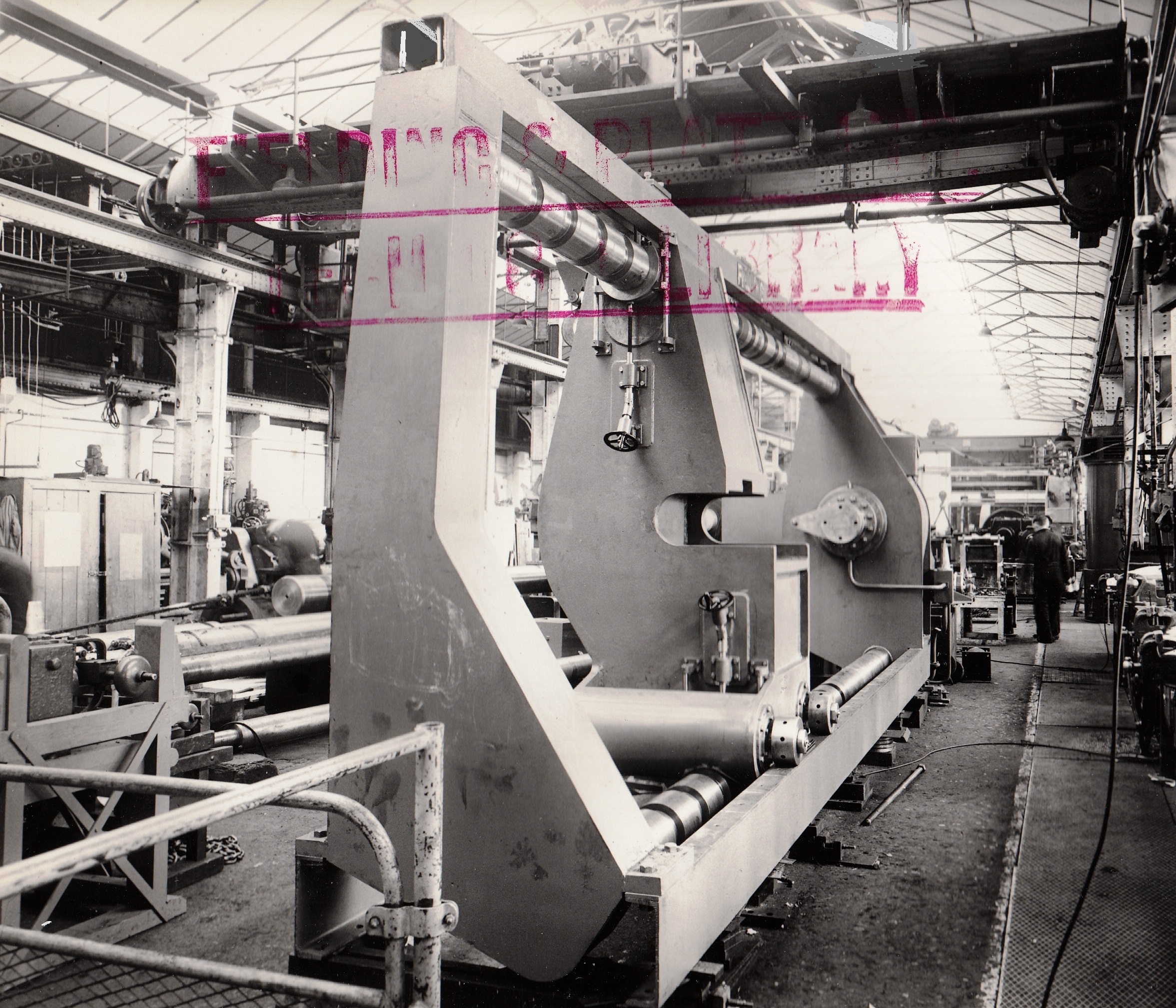
Chippy, thanks for a very detailed description of how the ‘clamps’ worked and your involvement. Was it George, or Gilbert Claridge who did the high pressure tests? George was in the Drawing Office, whereas Gilbert was in the Acceptance Dept. You, and others, may also care to look at the Photos of the Heavy Machine Shop and Fitting Shop, c.1954 & 1958, that illustrates the ‘clamp’ you have so ably described.
Hi John You are so right about George and Gilbert Claridge, thank you for pointing this out. Why I said George in my piece I just don’t know! Sorry for putting George and Gilbert in the wrong places, so to speak. Chippy Aston
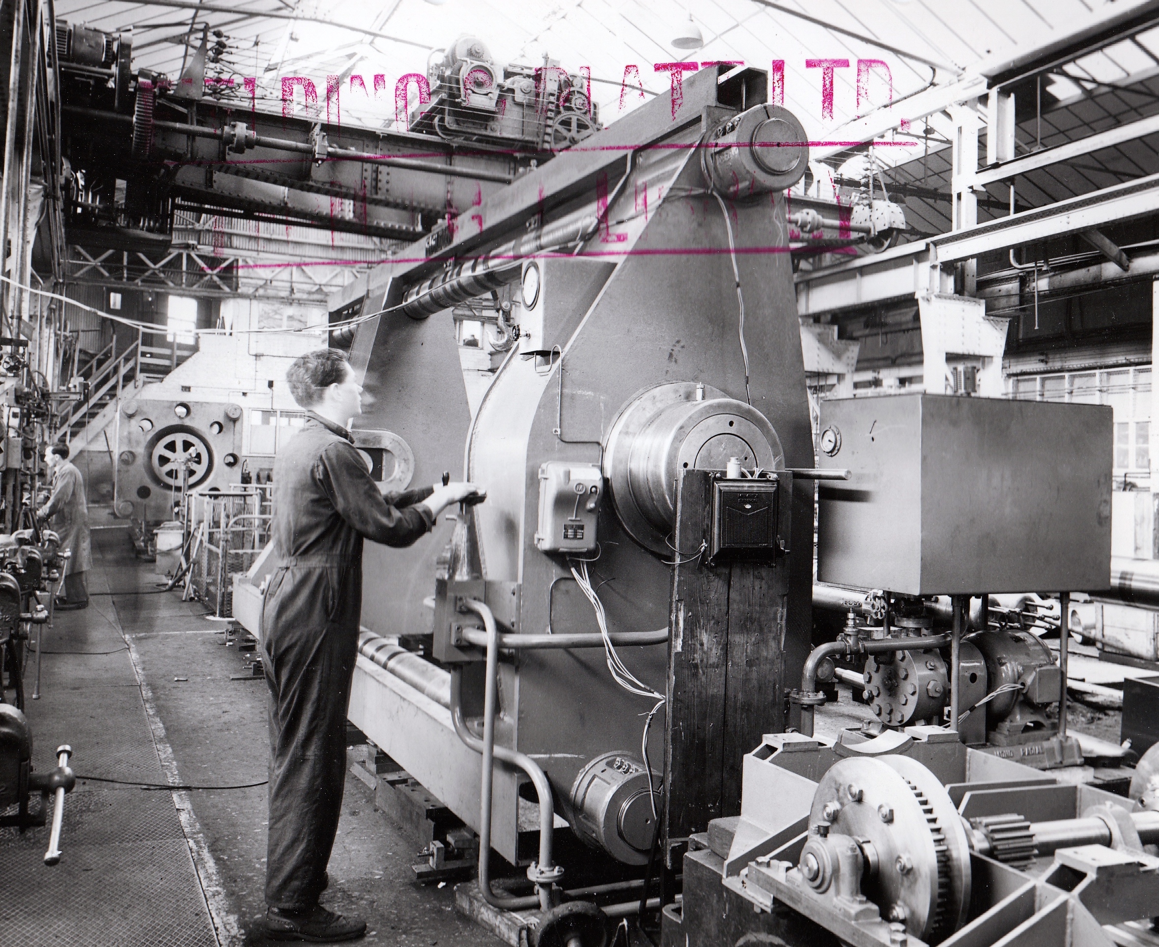
To the right of the press on the first photo is Mel Phelps. On the second photo, it could be Gerald Richings? Frank Ravenhill is correct.
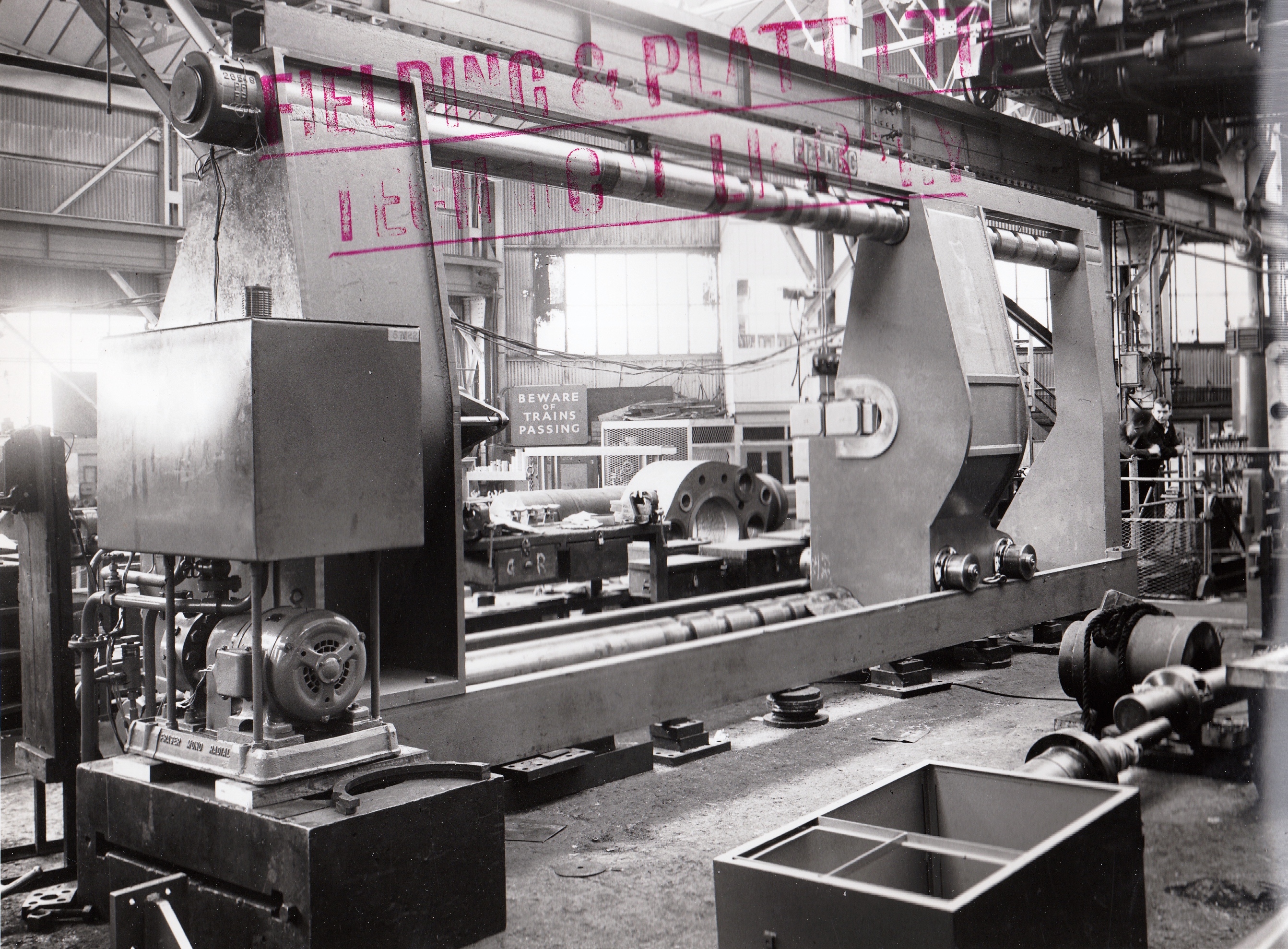
Hi Ollie, the ‘clamps’ were in photo 2. The ‘clamps’ comprised 2 very heavy pieces of steel that resembled the ‘end housings’ of an extrusion press, separated by 4 columns/tie rods. The columns had grooves round them at intervals so that cylinders of different lengths could be tested. This would have been achieved by removing sets of ‘half rings’ from the grooves, thus enabling the ‘end housing’ to be moved along to what ever dimension was needed. The half rings could then be re-fitted into the grooves and located into recesses in the housing. Once a cylinder to be tested was in the clamps and pressurised it would push against the ‘end housing’ and thus could be tested to whatever test pressure was required. Pieces of steel packing were used to make up any slight difference in length in the event that the dimensions of the cylinder didn’t quite match the space given by the housings and rings. There were smaller ‘clamps’ that were used to test some of the smaller cylinders as the large set would have been far too big. We had a portable pump and oil tank that could be moved around the fitting shops to where it was needed for testing purposes. I seem to remember that the cylinder being tested would usually have the ram only part way because otherwise it would take a lot of oil to test it and the tank on the test pump only held so much oil. With the test pump and tank came lengths of copper pipe, 3/8ths in diameter with nuts either end. Where they had been used so many times they were quite twisted and a pain to use sometimes! The test pipes would be connected to the cylinder and the pump with a 1/2″ BSP equal connector. The test pressures would always be higher than the working pressure, that was so that the test was effective at finding out if the part was faulty or not. The main cylinders on the ‘stone plant’ presses which I worked on quite a lot had a working pressure of 2240 lbf per sq inch, and that gave 400 tonf over the mould area of the pressing head. I once worked on an ‘intensifier’ that was being refurbished in the fitting shop and had to test it, but as it had to be tested up to a very high pressure I only took it up to I think about 20,000 psi, or maybe a bit more. This wasn’t tested in the ‘clamps’ as it was a complete assembly and had to be done where it stood. Then, at the weekend while the workshop was empty, one of the engineers, George Claridge went in and took it up to it’s test pressure which was very high. I don’t remember how high that was, but it was a lot higher than what I was allowed to do myself! It was done like that for safety reasons. We did have SOME health and safety then you know! George Claridge was a very nice and knowledgeable man. Hope all this makes sense! Chippy Aston
Thanks Chippy, are the clamps you’re referring to in the background of the first photo? Would be interested to know what the testing process for the hydraulic cylinders was and how the clamps were used? Cheers, Ollie
In the second photo, the man operating the press could be Nigel Coote, but that is a bit of a guess, and the other person may be Frank Ravenhill, Chargehand of Hydraulic 1.
The piece of equipment you can see in the background is a set of “clamps”, that were used for testing hydraulic cylinders in, prior to them being installed into presses. Chippy Aston
Add a comment about this page